
Introduction
Every day, fiber optic networks carry terabytes of data across cities, countries, and oceans, powered by lasers so intense they can permanently blind a person in a fraction of a second. These invisible beams travel at wavelengths that the human eye cannot detect, making accidental exposure during maintenance especially dangerous. This is where Automatic Power Reduction (APR) plays a vital role.
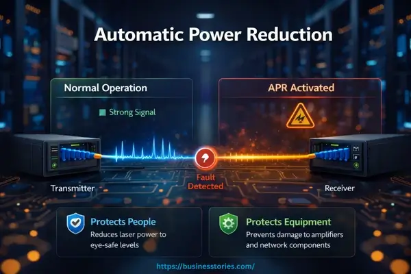
Automatic power reduction is a built-in safety mechanism in modern optical communication systems that detects abnormal conditions, such as a fiber break or accidental disconnection. It instantly reduces or cuts laser output to safe levels.
In high-power Dense Wavelength Division Multiplexing (DWDM) networks and amplified transmission systems, the output power often exceeds +20 dBm at the booster outputs. Without APR, the system would leave that energy exposed and uncontrolled at the point of failure.
Modern standards like IEC 60825 and ITU-T G.664 define strict safety guidelines. It ensures that optical systems remain within safe exposure limits.
In this guide, you’ll learn:
- How APR works in real-world optical networks
- Why it’s essential for safety and compliance
- Practical implementation strategies
- Key differences between APR, ALS, and APC
Whether you are a network engineer, a field technician, or someone entering the world of optical communications, this complete guide will equip you with the knowledge to understand and confidently apply APR.
What Is Automatic Power Reduction (APR)?
Automatic Power Reduction (APR) is a safety and compliance mechanism integrated directly into optical transceivers, Erbium-Doped Fiber Amplifiers (EDFAs), and optical line cards. Its primary function is to continuously monitor the integrity of the fiber optic link.
And, upon detecting a fault, autonomously reduce laser transmit power to an eye-safe level, typically classified as Class 1 under international laser safety standards. Think of APR as the circuit breaker of your optical network. Just as a circuit breaker disconnects an electrical supply the moment it detects an overload or fault, APR intervenes the moment it senses a fiber disconnection, break, or dangerous reflection.
The response is rapid, often within milliseconds. So there is virtually no window of time during which hazardous optical power remains accessible at the open fiber end.
How APR Differs from Automatic Power Control (APC)?
A common source of confusion is the distinction between APR and Automatic Power Control (APC). They are related but serve entirely different purposes:
- APR is an emergency safety response. It activates only when a physical fault occurs, such as a disconnected connector, a severed cable, or abnormal back-reflection. Its purpose is to protect people and equipment during failure events.
- APC is a performance management function. It continuously fine-tunes the laser drive current in small increments to maintain a stable, consistent output power as operating conditions change (temperature, aging, and voltage fluctuations). Its purpose is to ensure signal quality during normal operation.
Both systems are necessary in a well-designed optical transceiver, but their roles are complementary rather than interchangeable. A professionally designed module needs APC to maintain quality during operation and APR to protect against hazards when something goes wrong.
Why Automatic Power Reduction (APR) Matters in Modern Networks?
Modern high-speed optical networks operating at 100G, 400G, and even 800G rely on Class 3B and Class 4 laser sources. These lasers are categorized as hazardous because uncontrolled exposure can cause immediate, irreversible eye damage.
The light used typically in the 1310 nm to 1550 nm infrared range is completely invisible to the naked eye. A technician who unknowingly picks up an active fiber connector can suffer serious injury with no visible warning whatsoever. APR is the engineering safeguard that prevents exactly this scenario.
How Automatic Power Reduction Works: The Detection and Response Process
Understanding the mechanics of APR helps both engineers and technicians appreciate why it is a reliable safety layer, not just a regulatory checkbox.
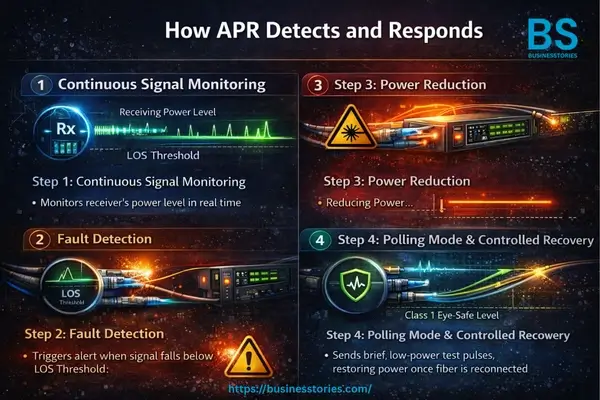
Step 1: Continuous Signal Monitoring
Every optical transceiver or amplifier equipped with APR continuously monitors the incoming receive (Rx) optical power level. This monitoring happens in real time. The system compares the current received power against a pre-defined threshold known as the Loss of Signal (LOS) threshold. As long as signal levels remain above this threshold, the system operates normally at full transmit power.
Step 2: Fault Detection
When the received signal drops below the LOS threshold, it indicates a fiber break, disconnection, or severe attenuation. The APR logic on the receiving module immediately concludes that a fault has occurred on the link. For Erbium-Doped Fiber Amplifiers (EDFAs), a secondary detection method called “optical back-reflection monitoring” is also used.
When a fiber is cut or disconnected, the reflectivity at the open end changes significantly. The system monitors the optical return loss (ORL). If the ORL drops below a fixed threshold, typically 17 dB in many vendor implementations, the APR alarm is triggered.
Step 3: Power Reduction
Upon detecting a fault trigger, the system immediately instructs its transmitter (Tx) module to reduce or cease high-power laser emission. The laser output drops to a Class 1 eye-safe level, or in some configurations, shuts down entirely.
This reduction must happen swiftly. ITU-T G.664 specifies that power reduction must be completed within 3 seconds of a fiber continuity interruption. A requirement derived from the Maximum Permissible Exposure (MPE) limits defined in IEC 60825-1 for 1550 nm radiation.
Step 4: Polling Mode and Controlled Recovery
To avoid locking the link in a permanently offline state after the fault is resolved, the APR system enters a polling mode. The transmitter periodically sends brief, low-power optical “heartbeat” pulses at safe power levels to check whether the remote link has been restored.
Once the heartbeat is received by the far-end module, confirming fiber continuity has been re-established, the system initiates a controlled, gradual power restoration sequence. This prevents a sudden power surge on the restored link. It ensures that all downstream amplifiers are safely stepped back to full operational power in a coordinated manner.
International Standards Governing Automatic Power Reduction (APR)
APR does not operate in a regulatory vacuum. A well-defined international standards framework governs its design, implementation, and performance requirements. Understanding these standards is essential for anyone deploying or maintaining optical equipment in commercial or carrier-grade networks.
1. IEC 60825-1: The Laser Safety Foundation
IEC 60825-1 is the foundational standard for laser safety. It defines hazard classes for laser products, ranging from Class 1 (safe under foreseeable conditions) to Class 4 (the most hazardous).
It also specifies Maximum Permissible Exposure (MPE) values, the maximum level of laser radiation that a person can be exposed to without sustaining injury. These MPE values form the scientific basis for determining how quickly APR must respond.
2. IEC 60825-2: Application to Optical Fiber Systems
IEC 60825-2 (currently in its fourth edition, published in 2021) applies specifically to installed optical fiber communication systems. Unlike IEC 60825-1, which classifies individual laser products, IEC 60825-2 requires a hazard level assessment at each accessible location across the entire fiber link.
This standard explicitly permits the use of APR techniques as a means of achieving a lower, less hazardous operational classification based on the optical power level in the fiber and the speed of power reduction. This is the standard that makes APR not just a best practice but also a compliance requirement for hazardous-power optical deployments.
3. ITU-T G.664: Network-Level Safety Procedures
ITU-T G.664 translates the IEC 60825 requirements into actionable, network-level operational procedures. It specifies:
- When to initiate automatic power reduction
- How quickly must the reduction be completed (within 3 seconds)
- How to safely restore full transmission power after a fiber repair
- Procedures for both SDH systems (using automatic laser shutdown, or ALS) and DWDM/amplified systems with Raman amplification
The standard also clarifies the terminology around Automatic Power Shutdown (APSD), an older term that has largely been superseded by APR in modern usage, though the two are functionally similar.
4. IEC/TR 61292-4: Optical Amplifier Safety
This technical report provides supplementary guidance on maximum permissible optical power for optical amplifiers, including Raman amplifiers. It addresses thermal damage, fiber fuse propagation, and connector contamination hazards, all of which become significantly more serious at the high power levels used in modern amplified transmission systems.
APR vs. ALS vs. APSD: Understanding the Differences
The optical networking world uses several terms that are closely related but technically distinct. Misunderstanding these can lead to compliance gaps or configuration errors.
Automatic Power Reduction (APR)
APR reduces the optical output to a lower but not necessarily zero power level. The residual power is brought within a safe hazard classification, typically Hazard Level 1 or 3A as defined by IEC 60825-2. APR is the preferred mechanism in amplified DWDM systems.
Raman-amplified links because it preserves some signal continuity during fault events, allowing the system to poll for link recovery without fully going offline.
Automatic Laser Shutdown (ALS)
ALS performs a complete shutdown of the laser source. It is the historically older mechanism, widely used in single-channel SDH systems. While ALS provides absolute protection by eliminating all optical emission, it requires a more deliberate manual or semi-automatic restart process.
This makes it less suitable for large-scale DWDM systems with dozens of channels and multiple amplifier stages, where a full shutdown would have a wider service impact.
Automatic Power Shutdown (APSD)
APSD is essentially an older, vendor-specific term for what is now more commonly called APR or ALS. ITU-T G.664 acknowledges the term but has standardized on ALS as the primary terminology for complete shutdown, while APR refers to partial power reduction. Understanding this historical naming context is useful when reviewing older vendor documentation or legacy network configurations.
The key practical distinction: In most modern amplified optical networks, APR is the preferred approach because it balances safety compliance with operational continuity. ALS is often reserved for access-layer or single-channel systems where the simplicity of a full shutdown is more appropriate.
Automatic Power Reduction (APR) in EDFA and Raman Amplifier Systems
APR takes on additional complexity in high-power amplified transmission systems, where protecting personnel requires coordinating safety responses across multiple network elements simultaneously.
EDFA-Based Systems
In DWDM networks using EDFA booster amplifiers, APR operates in a master/slave configuration. When the master amplifier, typically the booster at the transmit end, detects an open fiber condition via LOS or back-reflection monitoring. It enters APR mode and reduces its output power.
It simultaneously activates a hardware indicator (the APR mode pin) that signals all downstream slave amplifiers to reduce their outputs as well. This cascade ensures that no amplifier in the chain continues emitting hazardous power toward the open fiber end.
During APR mode in an EDFA system, several automatic operational adjustments occur: optical spectral equalization based on the optical channel monitor is suspended (to prevent incorrect adjustments on an underpowered channel plan). And certain alarms like “Gain Failure” are suppressed to avoid misleading alert cascades during the safety-constrained period. Importantly, back-reflection monitoring remains active throughout.
Raman Amplifier Systems
Raman-amplified systems and high-power unrepeatered submarine links present additional challenges. Raman pump lasers inject substantial optical power, often several hundred milliwatts to over one watt, directly into the transmission fiber in the 1450–1480 nm range.
Laser sources in this wavelength range emitting more than 500 mW are classified as Class 4 hazards under IEC 60825-1. ITU-T G.664 specifically requires that the APR in Raman systems must address both the forward-propagating DWDM signal channels and the backward-propagating Raman pump power. A dual-direction safety requirement that demands careful system design.
Automatic Power Reduction Alarm Troubleshooting Guide
APR alarm events on live networks are not always caused by actual fiber breaks. Understanding the common triggers and troubleshooting steps saves valuable time during network incidents.
Common Causes of Automatic Power Reduction (APR) Alarms
- Dirty or damaged connectors: Connector contamination is among the most frequent causes of increased back-reflection and spurious APR triggers. A single contaminated connector at a booster output can cause the ORL to fall below the 17 dB threshold, activating the alarm.
- Fiber disconnection during maintenance: Planned or accidental disconnection during patching or testing work.
- Misprovisioned amplifiers: Incorrect power provisioning can inject excessive power into the mid-stage dispersion compensation module (DCM) or fiber plant, triggering APR through an abnormal reflection condition.
- OSRP (Optical Span Recovery Protocol) events: Link down conditions triggered by intra-node fiber disconnections or amplifiers in out-of-service states can also activate APR.
Step-by-Step Troubleshooting
- Check the APR alarm details: Most network management systems provide an “Additional Information” field that gives a fault reason. Use this to identify whether the alarm is caused by a fiber break, a reflection event, or a provisioning issue.
- Inspect and clean optical connectors: Use an endface inspection tool on all connectors downstream from the alarmed amplifier. Clean any contaminated connectors with appropriate optical cleaning tools.
- Verify amplifier provisioning: Confirm that amplifier gain and power settings are within the designed operating range for the current channel plan.
- Isolate the fault location: Use Optical Time Domain Reflectometer (OTDR) measurements to pinpoint any fiber break or high-reflection point on the affected span.
- Test and restore the link: After resolving the physical cause, restore the fiber connection and allow the APR polling sequence to detect link recovery and initiate the controlled power restoration sequence.
Conclusion
Automatic power reduction stands as one of the most important safety technologies in modern optical networking. A quiet guardian that operates invisibly in the background but steps forward instantly when human safety is at risk. As fiber optic networks grow faster, more powerful, and more widespread, the role of APR becomes even more critical.
Understanding APR is not just a technical necessity. It is a professional responsibility for anyone who designs, deploys, operates, or maintains high-power optical infrastructure. The international standards framework, IEC 60825-1, IEC 60825-2, ITU-T G.664, and IEC/TR 61292-4, provides a solid, rigorously tested foundation for implementing APR correctly.
Following these standards, maintaining equipment properly, and understanding how APR interacts with related mechanisms like ALS and APSD ensures that your network remains both high-performing and safe. APR is your first line of defense against invisible laser hazards, and it only works correctly when it is properly implemented, maintained, and understood.
If you are deploying or upgrading optical transmission infrastructure, now is the time to audit your APR configurations and verify compliance with the latest editions of IEC 60825-2 and ITU-T G.664. It ensures that every team member who handles live fiber understands the safety mechanisms protecting them.
Frequently Asked Questions (FAQs)
Q1: What is Automatic Power Reduction in fiber optics?
Automatic Power Reduction is a safety mechanism that reduces laser output power when a fiber fault is detected, preventing harmful exposure.
Q2: How is APR different from Automatic Laser Shutdown (ALS)?
APR reduces power to safe levels, while ALS completely shuts down the laser during severe faults.
Q3: Why is APR important in DWDM systems?
DWDM systems operate at high optical power levels, making APR essential to prevent eye injuries and equipment damage.
Q4:Does APR affect network performance?
No, APR operates independently and does not impact data transmission or latency during normal operation.
Q5: What standards govern APR implementation?
APR is guided by standards like IEC 60825 and ITU-T G.664, ensuring safe optical network operations.

Tabassum Shaik is an Author, Researcher, and SEO Specialist with 8+ years of experience creating informative content on business, startups, entrepreneurship, marketing, technology, and digital trends. She focuses on sharing accurate, practical, and easy-to-understand insights for readers.